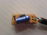
In any case, assembly of the circuit itself was almost trivial. In the picture (which my camera-phone had a hard time focussing on correctly), the thermistor is the small blob on the left, the diode is above and the electrolytic capacitor is below. A mini-DIN-8 cable connects the flow-control lines and ground to a serial port on the Gumstix, in theory.
|
| R = | -t |
| C ln(1 - Vc / V) |
The thermistor equation is R = R0 eB/T - B/T0, or
| 1 | = | 1 | + | ln(R / R0) |
| T | T0 | β |
Since, given the measured time, we can calculate R using the charging equation, calculation of temperature follows from the relation above. (The precision is dependent on the tolerances of the components used, however in practice the variation is about ± 5%.)
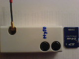
For the unfamiliar, the Gumstix is a tiny Linux-based computer with an ARM processor, quite a lot of memory, the aforementioned serial ports and, in my case, a Bluetooth module. Various configurations exist, mine is a Waysmall.
In the picture below, the Bluetooth antenna is visible on the upper-left and the serial ports at the lower-right. For scale, next to the case is an SD-card, for which there is a socket on the top side, above the serial ports.
 |
Gumstix is also legendary for the quality of its documentation. It comes with none. (None!) There is however a support wiki and I am not alone in remarking that in some cases, this is worse than having nothing at all. Take, for example, the helpful Serial cable connections diagram. See those pins labelled CTS and RTS? You'd think that this indicated that the serial port had hardware flow-control wouldn't you? You would, and you'd be wrong. Try searching its mailing list for the topic "hardware flow control" and you'll see that this is a major source of confusion.
(For the advanced student, try
determining which of the ports brought out on the case is
/dev/ttyS0,
i.e., the system console, and which is, err, the other one, using the
documentation wiki alone. For bonus points, repeat, in order to
determine whether the "other one" is /dev/ttyS1,
/dev/ttyS2, or /dev/ttyS3. Hours of
fun for all the family!)
Anyway, if you're still listening, the answer to the posers above is
/dev/ttyS2. (Thank you for playing!)
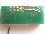
After even more perusal of the mailing lists, this diagram was discovered; it's the pinout labels of the pads on the bottom of the ST-UART serial board.
 |
This means that we can simulate DTR with echo "GPIO out
set" > /proc/gpio/GPIO83 and
then polling /proc/gpio/GPIO84 until it reads
... set. (I know, I know, polling is sub-optimal but I
don't think there is a choice at the moment, short of rewriting the
device-driver to support select().)
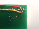 |
The picture above shows a close-up of these pads connected to the correct pins on the serial port. Note that these are TTL-level signals, so if a real RS-232 device is connected, it will probably fry the ST-UART board. (Memo to self...)
  FILE *mosi = fopen("/proc/gpio/GPIO83", "w");
  struct timeval start, end, dt;
  char buf[80];

  fprintf(mosi, "GPIO out set\n");
  fflush(mosi);
  if (0 > gettimeofday(&start, 0)) {
    perror("gettimeofday");
    return -1;
  }
  for (;;) {
    FILE *miso = fopen("/proc/gpio/GPIO84", "r");
    fgets(buf, sizeof(buf), miso);
    fclose(miso);
    if (strstr(buf, "set"))
      break;
    usleep(50000);
  }
  if (0 > gettimeofday(&end, 0)) {
    perror("gettimeofday");
    return -1;
  }
  fprintf(mosi, "GPIO out clear\n");
  fclose(mosi);
  dt.tv_usec = end.tv_usec - start.tv_usec;
  dt.tv_sec = end.tv_sec - start.tv_sec;
  if (start.tv_usec > end.tv_usec) {
    dt.tv_usec += 1000000;
    dt.tv_sec--;
  }