|
School of PhysicsTel:+353 1 8961675 Fax:+353 1 6711759 e-mail: physics@tcd.ie | |
|
Home News Introduction Schools Seminars Research Postgrad Courses Staff Other Sites Local |
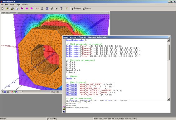
ManifestYou can download the standalone exe here (for Windows only). The user manual is here. Before you begin, remember this is not fully tested on all systems, but it works fine on all computers I've tested it on. Still, as an obligatory disclaimer, use at your own risk! If you're going to use it, read the user manual first to understand the scripting syntax (it's very similar to C++).
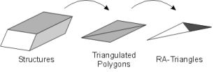
The program itself uses two methods for working out magnetic fields. The charge model, for designs composed entirely of hard materials, and the finite element model, for designs with soft magnetic materials. Charge ModelFor magnet arrays composed from uniformly magnetized segments of hard, magnetically transparent, permanent magnetic material it is possible to calculate the field using the magnetic charge model. Since the magnetization is fixed and uniform within each segment the calculation reduces to finding the field due to a scalar magnetic charge density on each surface of every segment. The surfaces of each segment can be broken into simplexes in which the entire magnet array can be expressed. The strategy for field calculation is to, firstly, find an analytical expression for the field created by an individual simplex then, secondly, to break the magnet array into simplexes and simply sum over all the simplexes to find the field at any required point. The advantage of this model is that it gives an extremely smooth field.
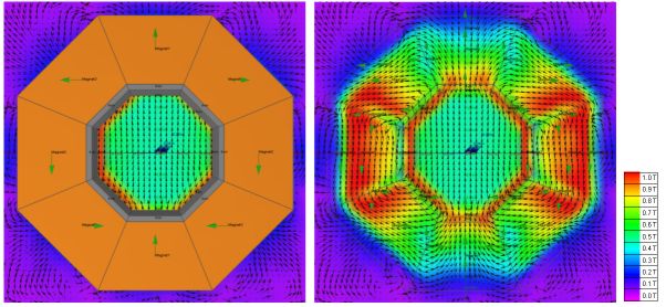
A simplex in 3D space is a triangle, and this can be broken further into two right-angled triangles (see above). Any design can then be represented in terms of simplexes of right-angled triangles. Once we found the solution for a right angled triangle, we could use this to express the field from any design by summing over all the simplexes within the design, subject to the appropriate 3D transformations. Finite Element ModelIn the finite element method, the domain of interest is divided into a number of simply-connected separate elements, or mesh. At the vertices of each element we need a good approximation to the exact solution, then across the element we can interpolate the solution from the values at the vertices. The approximate solution to our linear differential equation can then be expressed as the �stitched together� approximations from the separate elements within the mesh. The problem domain is often meshed using the tetrahedron (being the simplex in 3D) or, for example, quadrilaterals or hexahedral elements. Mesh generation for PDEs are typically more complicated than mesh generation for other types of applications (for example computer graphics) in that the mesh elements have to be �well shaped�. This is due to a number of factors; large angles in an element will cause errors in derivatives across the element as a consequence of interpolation, and small angles can also cause the matrix resulting from the discretization to be ill-conditioned . We need the elements to be as �round� as possible, that is (in the 2D and 3D simplex cases) to have the edges of any element as close in length to each other as possible. Mesh generation is not straightforward! Manifest uses the incremental Delaunay approach rather than the octree method or advancing front methods. The octree method proved to be difficult to implement due to the difficulties involved in resolving boundary/tree interfaces. The advancing front method was also difficult to implement due to the complex decisions to be made about vertex placement between colliding fronts. The incremental Delaunay approach, although difficult to implement in 2D, was attractive as many of the algorithms used could be extended to 3D relatively straightforwardly and of the three methods it has the least complex (and most elegant) set of rules for the placement of new vertices. NotesThe charge model works fine for any geometries but the mesh generator is a bit touchy as I ran out of time while writing it. It does, however, have the ability to mesh thin surfaces well by keeping a running track of the boundary elements and trying to immediately patch any it removes during the meshing process. The source code will be released as soon as I get a chance. I'm also planning to split the program into several chunks, which might be useful to people. The first chunk will be called ScriptBase, and will basically be the scripting window. You can use the scriptbase dll to create a script window in any windows application. You can then register callback functions in your program with the dll and have scripts call functions in your program. All the functionality of the scripting remains, e.g. variables, arithmetic, function handling, script linking etc. This should take all the work out of putting scripting into an application! The second chunk will be the 3d mesh generator. At the moment, this works, but not well for e.g. intersecting or other 'difficult' geometries. Mesh generators are notoriously difficult to get working and free 3D ones are notoriously difficult to find. Jonathan Shewchuk has written a very helpful guide in case you feel like writing your own. When I get the chance, though, I would like to re-write this using an advancing front technique combined with maybe a level set method. I spent far too much time on my mesh generator, and eventually it was de-prioritized in favour of actually getting results! If you do use this software, please let me know. And here's a fancy picture of the nice field diagrams it can create:
| ||||
|
Home | News | Introduction | Research | Seminars | Courses | Staff | Schools | Other Sites | Local |
|||||
Trinity College Dublin, College Green, Dublin 2, Ireland. Tel: +353-1-896-1000 |