The Design and Implementation of a 3D
Physically Enabled
Computer Game using Director 8.5, the Havok Xtra, and 3D Studio Max.
Morgan Brickley
Music
& Media Technologies
Department
of Electronic & Electrical Engineering
&
School
of Music
Trinity College Dublin

Submitted
as part fulfilment for the degree of M.Phil.
2002
Declaration
I hereby declare that this thesis has not been submitted as an exercise for a degree at this or any other University and that it is entirely my own work.
I agree that the Library may lend or copy this thesis upon request.
Signed: ____________________ Date: ____________________
Abstract
This report details the design and implementation of a 3D computer game developed for the Shockwave platform.
Key issues in the design and implementation of the application include:
· Using the Havok physical simulation system for enhanced game-play.
· Game character and level design techniques.
· Sound foley techniques and ambient sound design for computer games.
The report discusses the aims of the project, the challenges, and the outcome – the finished game.
Acknowledgements
I would firstly like to thank Fionnuala Conway for taking on the project, and giving me the chance to work on something I really enjoyed.
To the folk in Havok, for taking the time to explain everything from gimbellock to inertia tensors.
To my parents, apologies for spending too much time hibernating in the Lab.
To Rebecca Coyle, for proof reading the report and teaching me how to spell.
To everyone who ever played Frogger.
1.1 Introduction to the Report
Background Information & Chosen Technologies
2.2 Chosen Technology - Director Shockwave Studio
2.4 Chosen Technology – Native Instruments Reaktor 3.0
2.5 Chosen Technology – Propellerheads’ Reason
2.6 Chosen Technology – Stomper Ultra
2.7 Chosen Technology - 3D Studio Max
2.8 Key concepts of 3D graphics
2.10.2 Compound Objects
& Box modelling
3.2 The evolution of the Game Concept
3.6 The User Interface & Menu System
3.5.1 Design
principles of the menu interface
4.2 The Macro-view: How it all hangs together
4.3.6 The Raycast jeep
behaviour
4.3.8 The impose upper
limits behaviour
4.3.9 The hangback
tracking camera
5.2 Discussion of Sound Design in Computer Games
5.4 Sound Foley Techniques Used
6.2 The evolution of the game design
6.3 The ones that got left behind
6.4 Known Issues & Future Work
List of Figures:
Figure 2.2.1 Clockwise from top-left: The Stage, The Cast, The Control Panel,
3DPI and The Score.
Figure 2.2.2 Extract from Lingo script “Havok_goal”
Figure 2.3.1 A screen-grab from Director showing 3DPI and the control panel
Figure 2.4.1 A granular instrument set up in Reaktor3
Figure 2.5.1 The NN-19 Sampler from Propellerheads’ Reason
Figure 2.5.2 Screen-grab of Propellerhead’s Rebirth softsynth
Figure 2.5.3 The Rearview of a rack in Propellerheads’ Reason
Figure 2.6.1 A simple 80’s computer game effect setup in Stomper Ultra
Figure 2.7.1 The four viewports of 3D Studio Max (Top, Left, Perspective, and
Right)
Figure 2.8.1 A cube modelled as 6 meshes, consisting of two faces each.
Figure 2.9.1 A single time-step consisting of 5 sub-steps
Figure 2.9.2 Using two dashpots to form an axis of rotation
Figure 2.10.1 Convex, Concave and proxy objects
Figure 2.10.2 Firebird Character constructed as a compound rigidbody
Figure 3.3.1 Initial Character Designs (left) and first complete character
Figure 3.3.2 Firebird Character Profile
Figure 3.3.3 Magnito Character Profile
Figure 3.3.4 Brutus Character Profile
Figure 3.3.5 U-ship Character Profile
Figure 3.5.1 From 3D Studio Max (top) to patchwork levels to heightmaps (bottom
right)
Figure 3.5.2 A 25 by 25 Greyscale Heightmap and its resultant terrain
Figure 3.6.1 The main-menu and its child-menus
Figure 4.2.1 Table representing the cause-and-effect nature of the game engine
Figure 4.3.1 The setup of the catch behaviour
Figure 4.3.2 The setup of the rumble behaviour
Figure 4.3.3 The setup of the snitch behaviour
Figure 4.3.4 The setup of the AWOL behaviour
Figure 4.3.5 The setup of the goal behaviour
Figure 4.3.6 The setup of the raycast jeep behaviour
Figure 4.3.7 The setup of a heightmapped terrain
Figure 4.3.8 Setup of Havok_impose_upper_limits behaviour
Figure 4.3.9 Setup of the hang-back tracking camera
Figure 4.3.11 The camera options available in Director as shown by 3DPI
Figure 5.4.1 The final selection of sounds for the game
Figure 5.5.1 The four internal methods for playing sounds
Figure 5.5.2 Cause and Effect from a sound point of view
Figure 5.7.1 Snapshot of the travellizer granular synthesis instrument
Figure 5.7.2 Snapshot of the grainstate instrument – a sequenced granular synth
Figure 6.3.1 The psuedo-simulated snake character
Figure 6.3.2 An animated augmentation spinning around inside its physical proxy.
Chapter 1
Introduction
1.1 Introduction to the Report
This report serves not only as a testament to the work done but may also serve as a primer for the construction of 3D physically enabled games using the chosen technologies.
1.2 The Aim of the Project
The aim of the project is to develop a prototype for a full 3D computer game, using a 3rd party physics engine to enhance the game-play.
Typically a team working on a commercial 3D game would involve:
- 3D Graphic Artists (including level designers / character designers)
- 3D programmers
- A.I.(Artificial Intelligence) programmers
- 2D Artists
- Sound Artists
For large titles the bulk of the work is in the graphics department, but this game is intentionally designed to minimize the amount of artwork by setting it in an arena where the world size is limited. The areas this report concentrates on are:
· Creating interesting game characters with ‘physically active’ components.
· Developing with the 3D system in Director (i.e. using Lingo).
· Utilising the Havok Xtra to enable the ‘physics’ of the game world.
· Implementing the ‘Sound Design’.
1.3 Intended Audience
The report is aimed at anyone with an interest, professional or otherwise in learning about constructing 3D physically enabled games, especially if using the Havok system. The report assumes almost no previous knowledge in the fields of physics, graphics and the Director development environment, and as such those familiar with these areas may gloss over certain sections provided as introductions to these areas.
1.4 Report Outline
The report is divided into six chapters, and is laid out as follows:
This chapter serves as an introduction to both the report and the project.
Chapter Two – Background Information & Chosen Technologies
Chapter two discusses some background information relevant to the project and introduces the chosen technologies. It also serves as a primer to 3D modelling techniques and in-game physics.
Chapter Three
– Design
Chapter Five – Sound Design
Chapter five begins by commenting on some of the landmarks in game music, before looking at the sound system in the chosen technology Director, and then at the sound design for this project.
Chapter Six - Conclusion
The final chapter reflects on the initial aims, the development and the future of the project.
Chapter 2
Background Information & Chosen Technologies
2.1 Introduction
This chapter sets the scene for the report, discussing some of the key technologies employed in the realization of the project.
2.2 Chosen Technology - Director Shockwave Studio
‘Director Shockwave Studio 8.5’ is part of the Macromedia multimedia
software suite, and can be used for a great many purposes including the design
and construction of web-pages, interactive music CDs, etc. It can also be used to produce animations
and computer games, but so far most of these games have been implemented in 2D.
Any application developed in Director can be released either as a
stand-alone application (requiring no other software to run), or published on
the web in the form of a shockwave movie.
Although the term ‘movie’ is used by Macromedia, it is a misleading term
as the applications are almost always interactive. The shockwave movie standard can run on most Internet browsers
with the shockwave 8 plug-in, which according to Macromedia has an install-base
of 300 million. One of the main
advantages of writing games in Director is this ability to work cross-platform,
through the web browser on Windows, Macintosh and Linux operating systems.
(http://www.macromedia.com/software/director/)
2.2.1 Why Director?
The C++ programming language is the de-facto standard for most applications where high-performance is an issue, and 3D game development is no exception. C++ is an extremely fast and powerful language, in which a variety of gaming-friendly tools have been written, the most notable of which being Microsoft’s own DirectX system which allows direct access to and control over elements such as graphics, sound and controllers (joysticks etc.). So why then choose Director?
Essentially, because it is a web-friendly, cross-platform WYSIWYG (What You See Is What You Get) development tool that can be used as a rapid-prototyping environment for proof-of-concept demos. You may have a novel idea for a game and wish to present a mock-up to a potential publisher. Director allows you to get something up and running within a short space of time. The latest incarnation of Director includes a 3D Graphics API (Application Programming Interface) that opens up the door to a whole host of possibilities involving interactive 3D content on the web.
2.2.2 Director 3D
The high performance 3D graphics engine was designed by Intel and is accessed through Lingo scripts, Lingo being the native programming language of Director. The Intel engine runs on top of whatever rendering engine is available on the host computer – if it is a PC you’ll most likely get the best performance out of the Microsoft DirectX7 renderer, but the ubiquitous cross-platform OpenGL renderer is also supported.
2.2.3 The Director Way
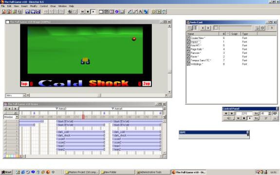
Figure 2.2.1 Clockwise from top-left: The Stage, The Cast, The Control Panel, 3DPI and The Score.
Director is not a programmer-centric tool like Microsoft’s Visual Studio, but more of a tool for artists and web-designers, with a mind to create interactive content. As such, Director works on a film analogy – the final application is termed a ‘movie’, all the elements are called ‘cast members’ and the construction of scenes takes place on a ‘stage’. We can see these elements in Figure 2.2.1, alongside the ‘score’, which is a means of sequencing the content being created. As cast members are dropped onto the stage they also appear on the score, and as the movie plays, a red indicator progresses through the score window to indicate which frame is currently being played.
2.2.4 Scripts & Handlers
-- GLOBAL DECALARATION
global gGoalModel
-- user definables
property pDisc
property pGoal
-- n.b. WORKS IN TANDEM WITH A GLOBAL SCRIPT
on beginSprite(me)
member("score1").text = "0"
member("score2").text = "0"
setGlobals()
end
on setGlobals(me)
global gGoalModel
global gDiscModel
gGoalModel = pGoal
gDiscModel = pDisc
end
Figure 2.2.2 Extract from Lingo script “Havok_goal”
Lingo scripts are the building blocks upon which the game is built. Over 70 custom scripts were written for this demo alone, controlling everything from the movement of the vehicles, to the generation of the landscape to the camera tracking. Figure 2.2.2 shows two handlers (beginSprite and setGlobals) taken from a simple behaviour script.
We mentioned that this script is a behaviour script, which means it can be attached to a cast member on the stage (i.e. a sprite) to enable that sprite to exhibit some behaviour. e.g. in order to get a 3D cast member to constantly rotate, a rotation script could be dropped onto the member’s sprite on the stage. Alternatively the script could be dropped onto a frame in the score thus becoming a frame script.
There are two other forms of script which have not yet been mentioned:
· Movie scripts are scripts that are not necessarily associated with one cast member.
· Parent scripts are similar to classes in object-oriented programming languages such as Java, in the sense that they encapsulate some functionality in a single script. A parent script may contain several different handlers that respond to different events but generally all the handlers will be related logically in terms of their function.
2.3 Xtras
Xtras are plugins for Director - extra functionality which can be added to the program. A typical game written in Director will probably use at least a dozen Xtras. The number of Xtras used has more of an impact if the game is explicitly being designed for the web, as some Xtras such as the Havok physics Xtra and the RaviWare joystick Xtra will have to be downloaded to the client before they can play the game. The greater the number of Xtras, the more likely the user will become tired waiting, and quit before the entire game is downloaded. On the positive side though, Xtras only need to be downloaded once, and are generally small due to Macromedia’s strict size constraints.
2.3.1 The Havok Xtra
The Havok Xtra for Director 8.5 allows the 3D world to be simulated physically. The game designer specifies properties for each element in the 3D world such as mass, the co-efficient of friction and restitution etc. and from there the physics system will detect and resolve any collisions that occur in the system. For example, setting up a snooker-game would simply involve drawing the table and balls in a 3D package and setting up the parameters to match those in the real world – the balls themselves are very smooth, so they would have a low co-efficient of friction, but the felt table provides grip and so would have a higher friction value. You can also allow events (such as a key-press) to trigger vector forces to be applied to an object, which you could use in the example above for a cue-stroke action. This affords us a new means of controlling objects, which gives a more indirect or arguably ‘natural’ feel to the gameplay. Instead of pressing the ‘a’ key to move a vehicle left by ‘x’ pixels, we apply a force in that direction and allow the physics engine to realise the outcome of that force.
2.3.2 The RaviWare D7 Xtra
The RaviWare D7 is an Xtra written to partially interface with Direct X 7.0, enabling joystick control, and supporting force-feedback joysticks. Force-feedback is a recent phenomenon in gaming and allows the controls on the joypad to resist movement, or to rock back and forth so as to simulate the confusion of a crash etc. The RaviWare Xtra however, unlike the Havok Xtra is not completely free. Although it will work completely in the Director environment, in order to build your application with the RaviWare functionality you must purchase and register a copy for $149.
2.3.3 The Multiuser Xtra
The Multiuser Xtra written by Macromedia allows Director movies to ‘talk’ to one another, by sending network messages to the other movies – be they on the same computer or on other known computers on the local area network (LAN). Director allows you to broadcast or multicast to a selection of movies, enabling LAN-based or internet-based multiplayer games to be an option when developing in Director.
2.3.4 The 3DPI Xtra
The 3D Property Inspector by Ullala is an extremely useful tool for inspecting the properties of any of the 3D models on screen. Among other things it will report the details of the model currently under the mouse pointer, and provide access to all models, texture maps, lights, cameras etc. present in the scene making it an invaluable debugging tool. It also compliments the Havok Xtra by providing real-time data from the physics system, such as the current linear and angular velocities, or any other variable in the physics system.
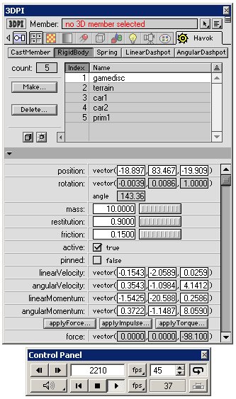
Figure 2.3.1 A screen-grab from Director showing 3DPI and the control panel
2.4 Chosen Technology – Native Instruments Reaktor 3.0
Reaktor is possibly the ultimate tool for sound artists. It is both a software-synthesiser and sequencer in one. Not only does it come with a large array of usable instruments but it allows you to build your own instruments by connecting up the various components such as wave generators, filters and envelopes to create substantial FM, AM, Subtractive or wavetable synthesisers. It also allows the creation of granular synthesis instruments such as the Grainstate instrument which was used to create ambient sonic landscapes in this project. The learning curve with regards instrument design is quite steep and requires an understanding of how analogue synthesisers operate, but the time invested is rewarded with some high quality soundscapes. It is an extremely deep tool, with high reusability and beautiful instrument interfaces.
(http://www.nativeinstruments.de)
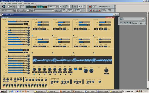
Figure 2.4.1 A granular instrument set up in Reaktor3
2.5 Chosen Technology – Propellerheads’ Reason
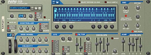
Figure 2.5.1 The NN-19 Sampler from Propellerheads’ Reason
Reason
is perhaps the more mass-market and instantly-accessible distant cousin of
Reaktor. Like Reaktor, it too is a
software synthesizer, but with a dedicated track based sequencer. It evolved from Propellerheads’ original
flagship program named Rebirth which emulated vintage Roland techno boxes,
namely the TB-303, the TR-808 and the TR-909.
Not only did they emulate the sound and nuances of these boxes to a very
fine degree but they also presented the interface in the same fashion as the
original units.
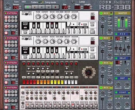
Figure 2.5.2 Screen-grab of Propellerhead’s Rebirth softsynth
Reason was an extension of this idea taken to the n-th degree. This time around they decided to present an entire studio, comprising of a rack into which you can hot-swap samplers, drum machines, mixing desks, effects units, subtractive synthesisers etc. The true power of the system is apparent when you flip the rack around to gain full access to the cable routing between units, where you can be as creative as you want when creating interest sounds without fear of frying some expensive studio equipment. Although the product may suit the range of ‘Dance’ genres, such as Drum’n’Bass, Techno, Trance etc. it can also be used just for the filters it provides on the samplers and effect units to create evocative sound textures.
(http://www.propellerheads.se/)
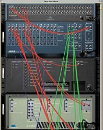
Figure 2.5.3 The Rearview of a rack in Propellerheads’ Reason
2.6 Chosen Technology – Stomper Ultra
Stomper Ultra is a simple sound design tool that allows sounds to be created using oscillators. The oscillators can be used either in series or in parallel and can also be used to modulate the frequency and/or amplitude of other oscillators, providing the user with some very early eighties sounding computer game effects. A handy slider bar allows you to change the shape of the frequency and amplitude curves and thus how the sound emerges over time.
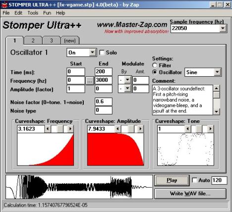
Figure 2.6.1 A simple 80’s computer game effect setup in Stomper Ultra
2.7 Chosen Technology - 3D Studio Max
Discreet’s 3D Studio Max is a complex 3D graphical modelling package, which enables the user to draw models in 3D. It is used in turns, for developing and animating characters for television and film, C.A.D. (Computer Aided Design), and for creating both characters and entire worlds for 3D computer games. The program has a stiff learning curve and a forbidding-looking interface with a plethora of menus, sub-menus, and sub-sub-menus, but thankfully it is a much used program and there is a great deal of help out there on the web at sites such as 3dcafe (www.3dcafe.com).
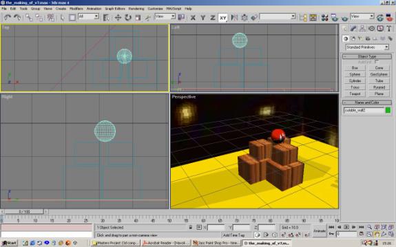
Figure 2.7.1 The four viewports of 3D Studio Max (Top, Left, Perspective, and Right)
2.8 Key concepts of 3D graphics
This section is provided to introduce some of the basic concepts and vocabulary of 3D graphics. Those familiar with the basics may wish to skip this section.
2.8.1 Polygon Meshes
Models in 3D graphics engines consist of a list of polygons, and for the most part in computer graphics, when we talk of polygons, we are really referring to triangles, which are by far the most implemented and supported polygon from both a hardware and software perspective. So, when we talk of a polygon mesh we are really just talking about a selection of triangles.
In Director, a model’s geometry is stored as a ‘model resource’ and in the case of a simple cube, this would consist of 6 meshes (one for each side of the cube) where each side (or mesh) is made up of two triangles (or faces). In figure 2.8.1 we can see that the points one, three and two make up one face, and the points two, three and four make up the second. It is important too, when defining a face, that we specify the points with an anti-clockwise winding, so that the renderer can easily figure out which side of the triangle is the front-facing and which is the back-facing. The model resource also contains a normal list and a colour list, which are used when shading the area inside the actual triangle.
|
Model:
cube1 Transform
= [position vector, rotation vector, scale vector] ModelResource:
Cube1resource MeshList
= [mesh1…mesh6]
VertexList
= [vertex1…vertex8] NormalList
= [normal1…normal8] ColourList
= [colour1…colour3] |
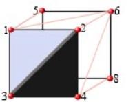
Figure 2.8.1 A cube modelled as 6 meshes, consisting of two faces each.
To complete this introduction to 3D graphics I’ll leave you with a few definitions:
Cloning:
Many
models can be created using the same model resource, to save on memory, and
this practice is referred to as cloning.
Transform:
Three vectors representing a model’s position, rotation and scale.
World-space transform:
A transformation with reference to the origin of the world.
Local-space transform:
A transformation with reference to the locus point of the model.
Caveat:
The mesh-face and vertexList paradigm is not the only system of representation used for 3D models - it is just the one that Macromedia chose for Director. Other systems might list the edges instead, to avoid problems related to shared edges.
2.9 A quick physics primer
When the physics engine is fired up first, it gets a copy of all the models to be simulated and converts them to rigidbodies. A rigidbody is essentially a superset of a model, in that it consists of a geometry (the model resource), a transform (the position etc.), and additional physical data, such as mass, friction and restitution values, velocities and accelerations etc.
The Havok physics engine works by looking at a rigidbody’s current position, velocity and acceleration and then projecting it ahead in time by a certain time-step, using fast integration based on the following formula:
Distance
moved = (initial velocity) + 1/2(acceleration)(time-step)2
It then checks to see if any collisions have occurred during the time-step, and if so it resolves them. This cyclical process is known as the simulation loop. The time-step is very small, because if the simulation is required to run in real-time, the time-step should be inversely proportional to the frame-rate. For example if we are running the application at 40 frames per second, then the time-step should be 1/40 second (0.025 Secs). Internally the system will typically take between 5 and 10 sub-steps to move forward to this point in time, as illustrated in figure 2.9.1. The sub-steps are essential when simulating fast moving objects, as if we do not sample the world at an adequate rate we may miss collisions and end up with rigidbodies passing through each other – the classic case of this being the bullet-through-paper problem, where collisions between fast moving bullets and paper-thin walls aren’t detected!
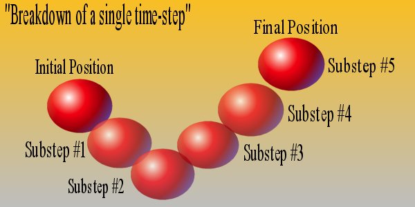
Figure 2.9.1 A single time-step consisting of 5 sub-steps
2.9.1 Forces and Impulses,
We mentioned earlier that it was possible to effect rigidbodies by applying forces to them at a point in their local space. We could, for instance, apply an upward force equal in magnitude to the weight of the rigidbody, at its center of mass, thus causing it to float – in essence an anti-gravity effect. We could then apply a force at a certain distance from the body’s center of mass, which would induce a torque or spin. Alternatively, if we would like more direct control over the body, for situations where we need instant response such as a drive model, we can use impulses instead.
2.9.2 Springs and Dashpots
In addition to being able to trigger forces and impulses on a body, we can also set up constraints between rigidbodies. The two types of constraints available in the Xtra are springs and dashpots, dashpots being very stiff springs, which bind two bodies together, while taking up no physical space themselves. For example, figure 2.9.2 shows how we can fix a door to a wall, by using two dashpots to represent the hinges. The door would then be able to pivot freely around the axis formed by the two dashpots.
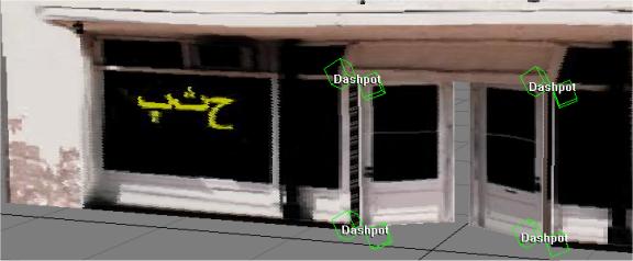
Figure 2.9.2 Using two dashpots to form an axis of rotation
2.9.3 Angular Dashpots
Dashpots also come in the angular variety – angular dashpots are used to constrain the rotation of one model to that of another. If you want a second door to always magically open when a first door is opened, you could place an angular dashpot between them. Not only can models be connected to each other but they can also be connected to points in world space. You may wish to fix a series of floating lamps to imaginary points in space but instead of creating them as fixed rigidbodies, placing a dashpot between them and points in space would mean that if you shot them they would rock back and forth casting eerie shadows over the scene.
2.9.4 Further Reading
For a more detailed explanation of the workings of the Havok physics engine see the document ‘Basic Physics Primer’ on the Havok website (www.Havok.com/Xtra)
2.10 3D Modelling Issues
Central to the model design philosophy was the issue of performance. In order to ensure the graphics renderer does not become a performance bottleneck, the models were designed to include as few polygons as necessary. Similarly, to ensure that the physics engine runs at full speed, we wish to reduce the number of concave rigidbodies in the system. A concave rigidbody is essentially one with a hole or a gap in it, which makes it more time consuming for the physics system to simulate. A donut is the classic example of a concave object. Cubes, spheres, and cylinders etc., on the other hand are all convex shapes. The reason being that at no point within a convex model can you draw a straight line that exits and then re-enters the model. You can easily see from the diagram then, that a donut is most definitely concave, as any line drawn from inside the donut through the center and onwards will bisect the shape 3 times. It is worth noting that fixed rigidbodies such as landscapes do not suffer a performance hit for being concave, and in fact are generally faster because the physics engines optimise based on the assumption that the landscape will be concave.
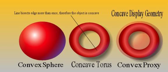
Figure 2.10.1 Convex, Concave and proxy objects
2.10.1 Proxy Geometries
Of course, there is nothing to stop you using one geometry for the displayed model and a separate but simpler geometry for the rigidbody. When a separate geometry is used for the rigidbody it is called a physics proxy. In figure 2.10.1 we can see how a torus could be represented physically as a sphere, although this would mean we would not be able to throw the torus onto a hook as other objects would not be able to travel through the center of it, so we may need to come up with another solution.
2.10.2 Compound Objects & Box modelling
Sometimes it is not possible to accurately represent a movable character with a single convex body, and in this case we may need to build characters out of a number of convex primitives. Such a model is termed a compound rigidbody.
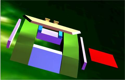
Figure 2.10.2 Firebird Character constructed as a compound rigidbody
A technique that lends itself well to both low-polygon counts and efficient physics is that of box modelling. Box modelling essentially involves constructing models out of basic primitives such as boxes, pyramids, spheres, cylinders, and so on, and then editing the mesh by selecting and moving individual vertices, or using modifiers, to scale, bevel, extrude and contort the primitive until they exhibit the required shape.
2.10.3 Reducing polygon count
Building models freely and without concern for the polygon count quickly leads to a scene with hundreds of thousands of polygons, which in turn means that the game will crunch on slower systems, thus limiting your accessible market. To reduce the polygon count for a particular model in 3D Studio Max we can:
· Use the Optimise modifier or 3rd party polygon reduction plugins such as PolyCrunch and Sony’s PolyEater. These give you a before and after polygon count, and allow you to achieve a balance between performance and model quality.
· Use the welding and deletion tools that come under the Geometry tab to hand-remove extra and unnecessary vertices, thus reducing the edge-count.
2.11 Summary
This chapter introduced the reader to the tools used in the realization of this project from Director 8.5, to the sound-design tools such as Reaktor and Reason, to the modelling package 3D Studio Max. The chapter also served as a primer to the basic concepts involved in 3D graphics and physical simulation.
Chapter 3
Design
3.1 Introduction
This chapter describes the design phase of the project and addresses the major decisions that influenced the direction of the game.
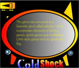
3.2 The evolution of the Game Concept
During the design phase of the project, the nature of the game changed on an almost daily basis, sketches of preliminary models were drawn up, studied, scratched out and drawn again. After an initial proliferation of ideas and feature wish-lists the game theme condensed down to a two player game of catch and chase. Players would chase a randomly moving disc, reminiscent of the snitch in Harry Potter, and having gained possession of it, try to shoot it at one of the moving goals. In order to steal the disc from the opponent’s grasp a player would have to forcefully crash into the opponent’s vehicle in order to rumble the disc-carrier and acquire the disc.
The game just described is essentially a proof-of-concept demo for a game that expands on the idea and brings it to the level of a multiplayer LAN-game, with teams competing against each other. At this level the game-play would really open up, as players would be required to jump, pass, shoot and coordinate tactics in order to gain the most points. The recent phenomenon of multiplayer network games provides testament to the fact that people certainly prefer to play against other humans than A.I. (Artificial Intelligence) characters. This game was an attempt to prove that the driving genre could also be brought into the multiplayer domain. While Codemasters’ Insane Racer included a multiplayer capture the flag mode, there is yet to be a team-based multiplayer game rooted in the driving genre.
3.3 Initial Character Design
|
|
|
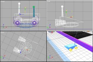
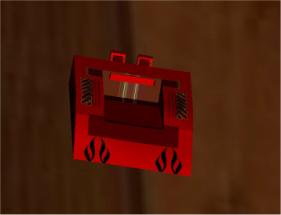
Figure 3.3.1 Initial Character Designs (left) and first complete character
After a time spent learning 3D
Studio Max, four distinct characters emerged from the construction yard,
designed with gameplay in mind. These
four characters, shown below in Figures 3.3.1 to 3.3.4 were named Firebird,
Magnito, Brutus and U-ship. The
character design philosophy was based on the paper-scissors-stone paradigm
where each character holds an advantage over some of the others, but also
suffers at the hand of some of the characters.
Firebird: Basic Features: Hi-speed. Low center
of gravity. Can overturn other vehicles by sliding under them and
force-flipping them. Invertible. Augmentation 1: Rear Mounted Thumpers propel the
disc from the bay at extreme speed. Augmentation 2: The floor of the disc bay is
spring-mounted for shooting the disc upwards to access higher platforms.
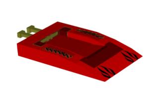
Figure 3.3.2 Firebird Character Profile
The Firebird was the first character
to be designed. It did not have any
wheels as it was expected to glide across the surface of the arena. With this is mind the front of the chassis
was designed so that if it ran into the disc, the disc would be fed into the
cut-away section of the chassis, which served as a containment bay for the
disc, where it would be fixed while the vehicle was in possession. The Firebird was designed so that two
methods of ejecting the disc would be possible. The first of these involved using the rear thumpers, pictured
above in yellow. The rear-thumpers were
attached to the chassis by means of dashpots.
It was thought that it would then be possible to apply an impulse to the
bumpers to shoot the disc, which would then be damped by the dashpot
system. The second method of release
involved the ‘fake’ floor to the vehicle which was free to rotate about an axis
formed by two more dashpots. Once again
a sufficient force applied to the base of this floor would turn the disc into a
projectile.
In later incarnations of the
Firebird, the structure of the vehicle was decomposed into a number of convex
primitives in order to satisfy the design criteria, with side-bracing impact
bars added to boot, again using dashpots.
At this stage however, possibly due to the number of dashpots operating
on the system the vehicle became unstable, and the forces acting upon it
spiraled to such an extent the vehicle would literally explode. So, it was necessary to backtrack, and
remove some of the additional functionality that had been added.
Magnito: Basic Features: Hi-speed, fast-turning, lo-skid,
invertible. Augmentation 1: Electro-magnet installed in the
disc bay fixes the disc in place until release. Augmentation 2: Can apply ‘super-forces’ to
other vehicles in collisions or magnetise her entire chassis to attach
herself to moving metal platforms.
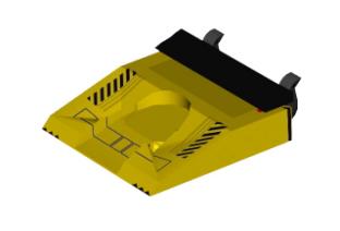
Figure 3.3.3 Magnito Character Profile
Magnito is a zippy character
intended in the long-run to be able to reach areas of the level that are
inaccessible to others, by magnetising its entire chassis in order to connect
itself to moving metal platforms etc.
It also introduced the concept of having area-of-effect magnets on the
vehicles – they did not necessarily have to touch the disc to take possession
but merely come within a certain threshold distance of the disc.
Brutus: Basic Features: Large and Heavy Vehicle. Augmentation 1: Front mounted Hoover can capture
disc and release it at angles of up to 45 degrees. Augmentation 2: Can swap hoover attachment for
bull-bars for some serious bullying tactics.
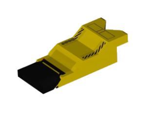
Figure 3.3.4 Brutus Character Profile
Brutus fulfilled the requisite thug
role for the game, and was intended for implementation in the team-version of
the game, where the teams’ tactics may require a leviathan tank of a defender
such as the heavy-weight Brutus to wait near the goal and dispossess any poor
striker of their goods.
U-ship: The U-ship can lock the
disc between it’s two arms, and release it by means of drawing back it’s
single thrust-bar. Augmentation 1: The arms of U-ship can
be upgraded to included thumpers which can be used for shooting the disc or
alternatively upsetting other players.
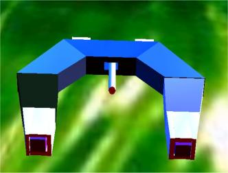
Figure 3.3.5 U-ship Character Profile
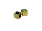
The U-ship was the first character
developed using the grouping mechanisms in 3D Studio Max to allow an otherwise
concave object to be constructed out of smaller convex primitives. The thrust-bar was attached to the grouped
model by means of dashpots and as such exhibited some very convincing secondary
motion. When the U-ship collides with
another character for example the thrust-bar vibrates, and takes some time to
come to rest due to the low damping, giving the definite impression that it is
an active element.
Augmenations: Found in virtually inaccessible areas of
the level or awarded for valiant playing, they ‘augment’.
The augmentations were a means of offering the players a chance to upgrade their characters mid-game. As the augmentations provide a distinct advantage, they may be worth chasing before going for the disc. The augmentations would either hover over a difficult jump or race around above the track requiring a well-timed jump to capture them. Although the character models were designed with augmentations in mind only the first augmentation was implemented for each character.
3.4 Evolution of the Game
Initially it was believed that everything should be done through the physics system. The thumpers were to be activated by a strong impulse and the various moving parts of the vehicles were to connected together using springs and dashpots. However, although there are endless possibilities for incorporating physics into the gameplay, sometimes there is merit in simply cheating, or should I say animating. The more dashpots acting on a character the higher the likelihood is that the character will become unstable, a state in which the character exhibits a jittery Shakin’ Steven’s type motion. If there is no advantage in simulating the thumpers then it is best to animate each required manoeuvre in 3D Studio Max and export. With this new angle, animations were created for the U-ship character’s thumper so that they would emerge from the arm, rotate through 720 degrees and then pull back inside. Thumper animations for the characters were also laid down in 3D Studio Max, and a constant spin, stop, and spin back animation was created for the augmentations. Much research was done in blending animation and physics, and a test scene created to prove that it was possible [PhysicsAnimBlender.dir].
The first major turning point in the game design was the decision to upgrade the drive system from the sliding block system (where the base of the character chassis touches the ground) to the raycast drive system, which allows models to hover at a certain distance above the ground. The attraction of the raycast drive model was that it seemed to be the best system available for coping with varied terrain, and the model incorporated 4 wheel suspension. The characters designed to prototype the raycast drive system were constructed through Lingo commands and these were the characters that made it through to the final demo (Figure 3.4.1). It was not known at the time that the speed of the raycast command would serve as a limiting factor in terms of networking the game. Nor was it realised that characters such as the U-ship would not work with the raycast drive model, because the raycast would fly right through them! Seeing as the prototype characters were in full working order, they gained acceptance as the two opposing characters in the game, distinguishable by the shape of their wheels.
|
|
|
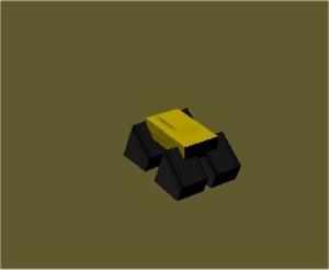
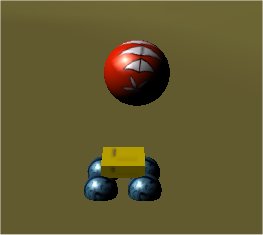
Figure 3.4.1 The two players characters that made it into the demo – both have Magnito’s area-of-effect magnets.
3.5 Level Design
The levels too, like the characters that travelled upon them, had that chameleonic characteristic. At first they were arenas full of ramps, gantries and obstacles to avoid, and then they became patch-work quilts of triangles generated randomly by custom algorithms. After the random terrains had had their glory days, heightmaps entered the scene, and for the moment at least, are here to stay.
|
|
|
|
|
|
|
|
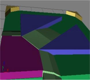
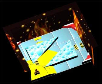
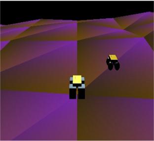
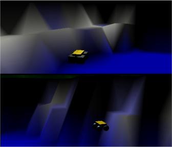
Figure 3.5.1 From 3D Studio Max (top) to patchwork levels to heightmaps (bottom right)
The reason for forsaking the arenas in the first place, was that the process of creating an arena in 3D Studio Max and then texturing it, was time consuming. Not all the features of 3D Studio Max are supported by Director’s exporter, so many things like textures may appear differently once inside the Director environment. More over, the scale of the world may have mysteriously changed, as 3D Studio Max stores all units internally in inches, and exports them as such, regardless of what unit you have selected in the viewports!
And so, an algorithm was written that would generate a mesh, given two opposite corner points, and a density parameter determining how many points would be used to make up the grid. Once this rectangular grid of equally spaced points was ready, another algorithm defined a height-value for each point on the grid. It would pick a random number between a base and a maximum and set the height of the point respectively. It was also possible to allow the height of the vertex’s neighbours to have an influence on the chosen height to allow for smoother hills.
The randomly
generated levels lent a whole new aesthetic quality to the game, with different
colours appearing each time you played, but it did not allow for levels to be
‘designed’. Enter heightmapping, a
technique based on sampling a greyscale image at periodic points to determine
the z-values (height values) for each vertex in the mesh.
The greyscale image
shown in figure 3.5.2 overleaf is a 25 by 25 pixel image, and in this case each
pixel dictates the height of an individual vertex in the terrain. The greater the density of points, the more
intricate the level can be but also the slower it will run. A projection of the terrain generated from
the heightmap accompanies the greyscale image.
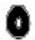
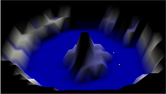
Figure 3.5.2 A 25 by 25 Greyscale Heightmap and its resultant terrain
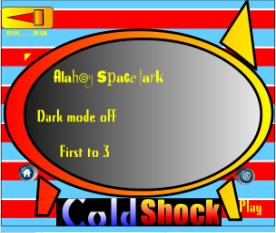
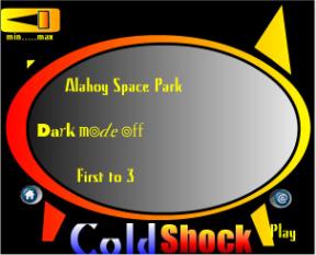
3.6 The User Interface & Menu System
It was mentioned earlier that Director is a WYSIWYG (what you see is what you get) application, meaning that you can drag and drop text and images onto the stage, see what they look like, make some changes and then if you are happy, save them. So, as far as generating menu systems is concerned, it is a gem. Strangely enough, it does not come with any menuing system, so it is up to the author to write all the menu-logic, and so rapid-prototyping the first time round, becomes not-so-rapid-prototyping.
The menu system was designed to be:
- Adaptable and Reusable
- Simple and Intuitive
- An aesthetic mix of new and old (retro)
- Accessible via keyboard or mouse
The following section
elaborates on each of these points in turn.
3.5.1 Design principles of the menu interface
- Adaptable and Reusable
In order to accommodate the possibility of alterations to the nature of the game at a later stage in development, for example to incorporate a LAN-based multiplayer mode, the design on the menu system had to be adaptable. A hierarchy of menu-option-choice was decided upon, where each menu kept track of which options were selected and each option remembered the active choice.
- Simple and Intuitive
It was imperative that the menu system be self explanatory, using symbols and graphical means to aid awareness of context. The currently selected option is written in a different font to make it obvious that that is the option selected. Arrows are used on either side of an option where it might not be obvious that there are other choices.
- A mix of the old and the new
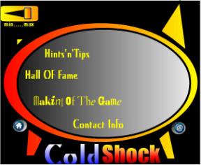
Although most of the original artwork for the menu was done in Director’s vector art editor, the menu also pays homage to Sinclair’s 1980’s home computer - the 48Kbyte ZX Spectrum. The loader screens, in front of which early-gamers spent hours in anticipation, are re-created here for those who care to remember. The scrolling text effects before each level are a throw-back to the era of scrolling demos, where programmers attempted to squeeze every inch of power out of their machines in an effort to push the boundaries through graphical rolling-demos.
- Accessible via keyboard or mouse
The interface can be navigated using the mouse or the arrow keys, which is a standard feature in most commercial games. Although director makes it quite easy to interact with the screen via mouse, the menu navigation via the keyboard was provided by a set of custom scripts that connect the menus in a logical fashion.
![]()
![]()
![]()
![]()
![]()
![]()
![]()
![]()
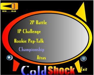
Main Menu
2Player Battle Menu 1Player Challenge Menu
Hints and Tips menu Xtras
Menu
Figure 3.6.1 The main-menu and its child-menus
3.7 The Sound-Design
Perhaps the biggest aesthetic turn-around during the game development
lifecycle resulted from fluctuations in
the nature of the sound design.
Initially, the focus was entirely rhythmic. A selection of complimentary poly-rhythms were composed in Reason
and exported as loops. These were
imported into Director and triggered during the course of the game. The idea was that you would have two pools
of rhythmic loops, one for each team, and as a team scores points, loops would
be selected at random from its pool and enter into the mix. As the game continues the musical texture
becomes increasingly deeper, creating tension.
By panning each loop based on the pool it came from, the players would
have a constant aural cue as to who was winning, so as to increase the
competitive spirit. Unfortunately, due
to unknown latencies and the limited number of sound channels available, this
approach had to be abandoned. This
caused far-reaching ripples in the nature of the game. Beats were out, and ambient textures were
in.
The ambient route was inspired by some of the mysterious and harsh
landscapes generated using heightmaps and colour blending. It was hoped to capture the desolate nature
of these stark landscape by means of granular synths, distorted wavetable
instruments and modular instruments.
The package of choice was now Reaktor, and the mood was darker than
originally intended.
The move toward ambient textures meant that the sound design as a whole
became more cohesive as the effects, music and voice-overs no longer seemed
disjointed, but reflections of the world-soundscape. The effects were intended not only to signify events but also to
provide cues into the nature of the world.
The jump effect gives the impression that we are dealing with large
machines, the crashes are pitch bent down and echoed to reflect the large
expansive levels, and the voice-overs are convoluted with haunting sirens to
add hints of the unknown.
3.6 Aesthetic U-turns
This turnabout in the sonic-plot, resulted in experimentations with
depth fogging, parented light sources and other techniques that accentuated the
mood of the music. Some of these
techniques are quite CPU intensive so they were bundled into the ‘Dark Mode’
option available on the main-screen.
The Darkmode places red depth fogs on both cameras and attaches lights
to the moving vehicles so that as they move through the world the colours
alter.
3.9 Summary
This chapter discussed the ambitious beginnings, the subsequent realisations of what was and was not possible, and the catalogue of turnabouts that defined the game’s evolution.
Chapter 4
Implementation
4.1 Introduction
This chapter is intended to pull
back the curtain and reveal the inner workings of the game engine.
4.2 The Macro-view: How it all hangs together
Everything happens for a reason, it
is said. Nowhere is this truer than in
the context of the game engine, the functioning of which is based on cause and
effect. In our game world, the causes
are primarily the players’ keystrokes and collision callbacks. A collision callback is a notification of a
collision occurring between two specified rigidbodies, witnessed by the physics
engine. These notifications are sent
only if an interest in two rigidbodies has been registered, using the Lingo
command Havok.registerInterest(). In
addition to scanning the controllers (i.e. the keyboard or joystick) for
events, custom events can be generated by polling parameters, such as a
player’s position or its angular velocity etc.
The area of effect magnet is implemented using parameter checking for
example – it simply checks to see if the disc lies within a certain distance of
the jeep. Table 4.2.1 lists some of the
causes and effects that occur during the game.
Please note that most common events thrown are the parameter checking
events, but only a selection of these are included in the table.
|
Cause (Event): |
Effect (Action): |
Keystroke events |
|
|
Keypressed(Arrow key) |
Apply impulses to drive car |
|
Keypressed(“P”) |
Apply boosting force |
|
Keypressed(“O”) |
Apply braking force |
|
Keypressed(“I”) |
Recreate disc as rigidbody,
release from control of vehicle, and apply forward force. |
Collision Callback Events |
|
|
Collision between (Jeep1, Jeep 2) |
If either jeep has possession of
the disc then recreate the disc as a rigidbody, release it from the control
of the jeep, and apply a rumble force to the disc. |
|
Collision between (Disc, Goal) |
Check the possession flag and
increment the score accordingly. Check to see if the score has reached the
winning score. |
|
Collision between (Jeep, Terrain) |
Trigger random sound fx from
CRASHfx |
|
Collision between (Jeep, Goal) |
Trigger random sound fx from
CRASHfx |
Parameter Checking Events |
|
|
Disc enters threshold distance
from Jeep |
Delete the rigidbody from the
system. Slave the disc model to the
jeep. Update the global possession flag. |
|
Players position is outside the
boundaries of the level |
Either reset to the start position
center or place at opposite side of level (wrap-around) |
|
Players angular velocity exceeds a
certain threshold |
Slow down the camera, impose
velocity damping so as to stabilize the vehicle. |
Figure 4.2.1 Table representing the cause-and-effect nature of the game engine
Let us take a look now at some of
the individual causes and effects.
4.3 The behaviours
The functionality of the game is served up as a selection of behaviours, each tackling one specific job. So, in theory, it is a modular approach, or even object-oriented. In reality of course there are a great many number of interdependencies between different behaviours and a large number of global variables (data available to all the behaviours) are used to allow behaviours to communicate. Each behaviour can optionally expose some of its parameters, encouraging programmers to move away from hard-coding values, and forcing them to describe in some fashion what the behaviour does. The interface to the catch behaviour, for example, is shown here in figure 4.3.1, providing the game designer with easy access to the important parameters so that he can tweak them to enhance playability.
4.3.1 The Catch behaviour
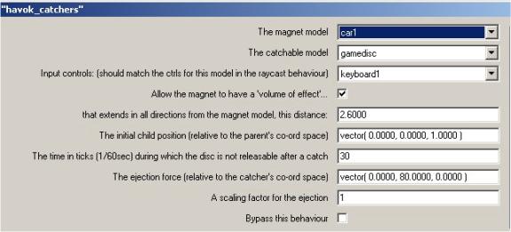
Figure 4.3.1 The setup of the catch behaviour
When the catch behaviour shown in
figure 4.3.1 is dropped onto a 3D sprite it identifies two rigidbodies in the
system. With each beat of Director’s
heart it subtracts the world position of the first from the world position of
the second and checks to see if the distance is less the distance 2.6
metres. This process of checking a
value on every frame is known as polling, and is generally less efficient than
callbacks, because 99.99% of the time, the answer returned is no (or false). If the answer is yes, the disc’s rigidbody
is destroyed so that the disc can be slaved to the vehicle. Slaving in Diretor is termed parenting,
where a parent (the car) dictates the position of the child (the disc). In fact we can see from the interface that
the child’s position relative to the parent is set to (0,0,1), so as soon as
the disc is caught it is placed one metre above the car’s center. [Aside: The
x,y,z axis in Director represent the horizontal, vertical and height axes
respectively ]
4.3.2 The Rumble behaviour
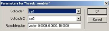
Figure 4.3.2 The setup of the rumble behaviour
The rumble behaviour registers an
interest between the two collidables specified. If a collision occurs and one happens to be in possession of the
disc then the rumble impulse is applied to the game disc. The only problem being that we destroyed the
disc’s rigidbody earlier when the disc became a slave to the catcher, so first
of all we must recreate the rigidbody for the game disc.
4.3.3 The Snitch behaviour
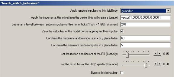
Figure 4.3.3 The setup of the snitch behaviour
The snitch is a blatant reference to
the elusive winged sphere that the seekers in the game of Quiddith must chase
in order to end the game and secure 50 points in the fantasy world of Harry
Potter [ROWLING J.K.] In this
implementation, random impulses are applied at a specified interval. Figure 4.3.3 also shows that a maximum
impulse value can be choosen for the xy plane and the z axis. As an extra, the designer can also set the
co-efficients of friction and restitution at this point, to allow for different
modes of play for different levels.
4.3.4 The AWOL behaviour
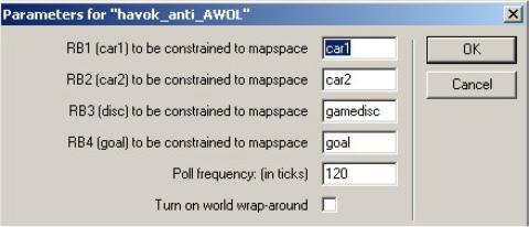
Figure 4.3.4 The setup of the AWOL behaviour
In order to ensure that the players
do not fall off the level and into the (almost) endless void, the options
available to us are to surround the level with four large invisible walls, to
limit the worldspace with physical planes or to poll the important characters
and game objects. The second solution
is perhaps the ideal solution, but planes are not yet available in the Havok
Xtra. Polling works well when there are
a limited number of bodies to keep track of, and is made more efficient by a
polling frequency which can be set in the interface in ticks (60 ticks = 1
second). In the example above the AWOL
script checks the positions of the game-models every two seconds, and if they
exceed the boundaries of the level it then resets them to their start
positions. If the worldwrap parameter
is selected, any rigidbody that falls off the left side of a level re-emerges
on the right hand side, and vice-versa.
4.3.5 The Goal behaviour
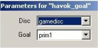
Figure 4.3.5 The setup of the goal behaviour
The goal behaviour uses collision
callbacks to register an interest between the goal and the disc. When the goal is struck, the collision
handler must firstly determine which vehicle shot the disc before awarding any
points. This information is stored in a
global possession variable, which gets set whenever a vehicle catches the disc.
4.3.6 The Raycast jeep behaviour
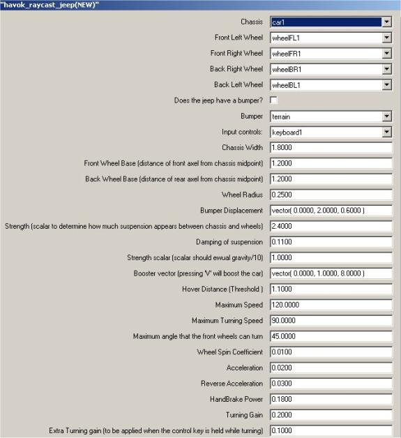
Figure 4.3.6 The setup of the raycast jeep behaviour
A raycast is the term used to
describe the act of firing a ray from a point in the 3Dworld in a particular
direction and seeing which models that ray intersects with. In our case this is a good way of
determining how far above the ground each wheel is. The raycast is also used by the visibility camera in determining
which models are obscuring our view of the main character and must be removed
or blended. It does so by shooting a
ray from the camera position towards the model we are interested in and
applying a transparency effect to any models encountered on route. The raycast itself is quite an expensive
command to call CPU-wise so it presents us with an upper limit on the number of
vehicles that can be implemented in the system.
4.3.6.1 The Raycast Jeep behaviour in depth
The raycast jeep drive model is a
modified version of the raycast car demo written by Havok. In order to tweak the model however, a full
understanding of how it works is imperative, so some space is given here to explain
its inner workings.
A quick look at the raycast jeep
script will reveal that there are really two pieces of code at work – one
allowing us to drive the jeep around, and one that allows the jeep to hover at
a certain distance above the ground.
The handlers I am referring to are:
·
updateHover
·
updateDrive
updateHover:
A good way of thinking of the hover
mechanism is to imagine the car chassis mounted on four separate springs. The springs provide the cars suspension or
‘hover’ based on a hover distance, a strength and a damping parameter. I’ll say more about these parameters later,
but for now, let us consider how the hover operation works:
In
the initHover handler, we determine the
midpoints of each wheel in local space (i.e. with respect to the chassis). These wheel points are then transformed into
worldSpace in the updateHover handler by multiplying their positions by the
current chassis transform. Now that we
know where the wheel midpoints are, we shoot a ray downwards to see what models
lie beneath. We then iterate through
this list of models checking whether or not any of these models are valid
models to drive on. If we find a valid
model in the raycast list and this model is within the threshold ‘hover distance’,
then this wheel is said to be ‘hovering’.
Only hovering wheels contribute to the driving of the vehicle.
updateDrive:
In order to drive the car we apply
various linear and angular impulses to the chassis. The impulses are all scaled by a ‘power coefficient’ which
represents the number of wheels that are touching the ground. As we said above, a wheel is touching the
ground if it is above the ground and within the threshold ‘hover distance’. The updateDrive handler also deals with
flipping the car if it is upside-down, applying drag, and compensating for
sliding and spinning.
4.3.6.2 Tuning the vehicle – the art of tweaking
From the vehicles point of view, the strength and damping parameters along with the hover distance parameter are what really determine how the vehicle drives. Seeing as we are working in the metric system using a real-world scale, the majority of the parameters such as the dimensions, top-speeds and acceleration can be set to match an average jeep. The suspension parameters however, are extremely hard to guess, and so a special tuner was developed for easing this process. The tuner uses the keyboard keys 1 to 8 to adjust the strength and damping in conjunction with the r which instantly resets the position of the car so the suspension can be observed as the vehicle drops onto the terrain.
tuner keys:
KEY 1 increase the STRENGTH by 0.1
KEY
2 decrease the STRENGTH by 0.1
KEY 3 increase the STRENGTH by 0.01 (FINE-TUNE)
KEY 4 decrease the STRENGTH by 0.01 (FINE-TUNE)
KEY 5 increase the DAMPING by 0.01
KEY
6 decrease the DAMPING by 0.01
KEY 7 increase the DAMPING by 0.001 (FINE-TUNE)
KEY
8 decrease the DAMPING by 0.001
(FINE-TUNE)
KEY R reset the position of the vehicle to the reset point specified in the behaviour properties.
4.3.7 The terrain generation
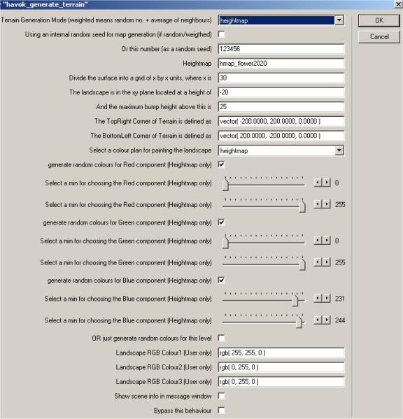
Figure 4.3.7 The setup of a heightmapped terrain
The terrain generation has already
been introduced in the chapter on design, and it is from there that we will
pick up the story. We have already
mentioned that there are three means by which terrain can be generated: random,
weighted random and heightmapping.
All three methods follow the same
procedure for generating the mesh:
- Firstly a list of vertices representing the terrain in grid form is created.
- The z-values are then altered in to follow either a random sequence, a weighted random sequence or the pixels of a specified greyscale image. To generate a random sequence a computer needs a seed, which can either be the clock, or a specified number. The same seed will generate the same series of numbers and so could be used as a means whereby users having found a seed that produces an interesting level could post the seed on the internet for others to use!
- A list of triangular faces is generated from the grid, by dividing each quadrilateral in the grid into two triangles. By convention each triangle is created with an anti-clockwise winding so that all triangles are facing the same direction.
- A colour list is generated for the mesh of three colours. Each vertex is assigned an index into the colour list, and all points between neighbouring vertices are shaded.
- Normals are generated for each vertex in the mesh. The normals are calculated to be perpendicular to the plane, but in the case of a vertex shared among many faces, an average is taken.
4.3.8 The
impose upper limits behaviour
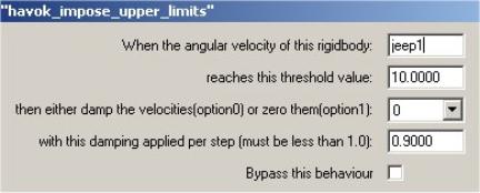
Figure 4.3.8 Setup of Havok_impose_upper_limits behaviour
The Havok_impose_upper_limits behaviour attempts to counteract
spiralling tumbles. Occasionally when
the car flips over, it starts to go into a series of tumbles, so you can use
this behaviour to attempt to detect when this is happening and then take
action. When the vehicle’s angular
velocity exceeds a certain threshold you can either completely zero the angular
velocities at this point or alternatively damp them. The behaviour can be reused to set multiple thresholds each with
it’s own damping value.
4.3.9 The hangback tracking camera
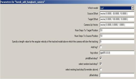
Figure 4.3.9 Setup of the hangback tracking camera
A good camera is one you do not notice. A bad camera on the other hand can make a game unplayable, so some time is dedicated to getting the camera just right. The camera chosen for this game was a projection camera that tracks using a target-source model. The source is the camera, and the target is the model to be tracked. You can see from the ‘source offset’ chosen in the interface, that the camera is located 30 metres behind the source model and 10 metres above it, and then ‘target offset’ parameter tells us that the camera is pointing straight ahead to a point 100 metres directly in front of it. This is visualised in 3D Studio max in Figure 4.3.10. How far it can actually see is determined by the yon parameter, and how much directly in front of it is ignored (its blind-area), is determined by the hither parameter. These are related to the far and near clipping planes, which help to define the viewing frustrum inside of which models are visible.
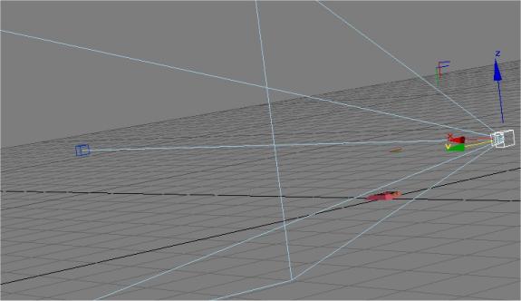
Figure 4.3.10 A perspective view of the tracking camera located at (0,-30,10) with respect to the target
Also apparent from the interface is a curious ‘number of steps to source’ parameter, and a similar one for the target. This is the speed at which the position and direction of the camera adjust. If the camera were just to immediately update it’s position and direction, the game would seem extremely action-packed but would perhaps be more difficult to play. By smoothly adjusting to the new position the camera lags slightly behind the movement of the character and becomes less obviously present.
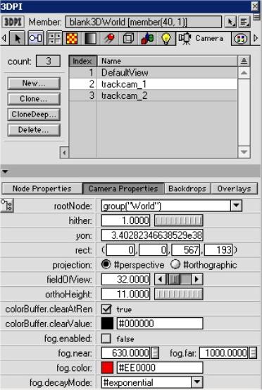
Figure 4.3.11 The camera options available in Director as shown by 3DPI
Figure 4.3.11 gives an insight into some of the parameters available to tweak when setting up a camera. The most important decision is the choice of camera type – perspective cameras exhibit fore-shortening, which means that parallel lines at an angle to the camera will converge on a point in the distance. Our own eyes work in perspective and so it is the natural choice. The field-of-view parameter determines how extreme this effect is. A large field of view will yield super-widescreen results, whereas a small field of view will mean that only a limited amount of the landscape can be seen from a horizontal perspective.
A bonus in Director vis-à-vis cameras is the ability to apply overlays and backdrops to the camera. Overlays are blended images that can be placed over the camera, which are ideal for HUD’s or Heads up display that show the important game statistics on screen. Using an animated sprite may allow effects such as rain and snow to be cheaply simulated. Backdrops on the other hand, are images that hang in the distance and do not change position as the camera moves. These are ideal for stars and cityscapes etc, lending that extra bit of authenticity to the world. Finally fog can be added for errie effects.
The hangback aspect of the camera is a modification that slows down the tracking once the target’s angular velocity exceeds a threshold value. This feature was introduced to stop the dizzying spinning that occurred when the target went into a rolling tumble or wipeout.
A final note deserves a mention with regard to perception, scale and camera positioning. Sometimes gravity seems too weak, even when it is set according to the units used to represent the world. Even though the frame-rate in Director is set so that the world runs in real-time, the vehicle seems to float once airborne. One reason may be that the actual frame-rate the game runs at will be determined by the specifications of the machine it is running on, so although the game designer may have specified a frame rate of 45fps (frames per second), an average of 30fps is actually achieved. Alternatively, the scale may be wrong. If we were to observe a plane falling out of the sky a kilometre away it would probably appear to be falling quite slowly, whereas a model plane dropped just in front of us would seem to drop at a much faster rate. Both the model and the real plane appear to be the same size too, and in the game environment because we have no reliable frame of reference we might conclude that in fact gravity is too weak. Altering gravity, however, makes everything heavier, which means that all the dashpots, springs and suspension system must be re-configured. As such the camera distance should be set to where an average human expects the camera to be. If this doesn’t allow enough of the game world to be seen, the field of view parameter should be adjusted.
4.4 Summary
This chapter attempted to provide a more in-depth vista into the
mechanics of the game. Initially
discussing the macro-view, the focus then turned to some of the more important
individual components of the project.
Chapter 5
Sound Design
5.1 Introduction
This chapter deals with the sound design for the game, which includes everything from the in-game sound effects, to the ambient world noise, the voice-overs and title-music.
5.2 Discussion of Sound Design in Computer Games
Different game genres naturally lend themselves to different types of music, from the insidiously catchy themes in platform games such as the Mario and Sonic series, to the college-rock and hip-hop that dominates the snowboarding genre, to the dark worlds of sound created by Trent Reznor of Nine Inch Nails for the Doom sequels.
The sound systems available to computer games have come a long way from the days of 4 channel 8-bit sound. But even in the early days, composers such as Shigeru Miyamoto were continually setting the precedent for sound and then raising the bar again with each new release. Miyamoto is responsible for some of the defining changes in the way sound interacts with a game. Having composed the title music for Donkey Kong as early as 1981 he went on to reset the watermark with Super Mario Bros (1985) and the Zelda Series (1987-1999). He recognised that the music could provide cues to the player that they would eventually come to depend on – such as the wearing off of invincibility, or the proximity of a nasty. He also recognised the need to compliment the pace of the game with the music, as demonstrated superbly in the various themes in Super Mario Bros.
Fast forward to the present day, where relatively high capacity storage devices such CD-Roms and DVDs enable composers to produce lengthy pieces for games. In some, such as Resident Evil, the soundscape is used to induce fear, in high-speed racers such as Wipeout the soundtrack is intended to get the adrenaline pumping.
Sound in games, just like in films, can help to establish a more convincing world. It can help to fill in the gaps and allow the player to better imagine the game-world which surrounds them. In a game such as this, without a team of graphic artists to create a graphically detailed world, much is relying on the soundscape to suggest to the player where indeed they are. It is the sound that provides the player with a richer impression of the world, making it seem deeper than just a polygon soup.
5.3 Sound in Director
Director features a basic sound interface that allows 8 channels of
audio, with panning, volume control and looping. It also allows the playback of audio files compressed using
Macromedia’s implementation of the MPEG-Layer 3 sound compression codec, which
go by the name of ShockWave Audio (SWA) files.
As a bonus, it is possible to identify markers inserted into an audio
track in Sonic Foundry’s Sound Forge, so as to enable syncronisation between
the audio and other elements. In a
multimedia storybook for example, this could be used to update a page of text
when the speaker in the audio file gets to a specific word etc.
In order to get the maximum value out of the PC’s soundsystem however, a
purchase of the DirectSound Xtra ($185) would be necessary. It exposes the Microsoft DirectX Sound API,
which allows real-time pitchshifting, 3D positional audio and direct access to
the soundcard. When using the 3D audio,
each sound source has both a position and a velocity, as does each listener
defined in the system. Effects such as
the Doppler effect fall out of the
system without any great effort on the programmer’s part. Having direct access to the soundcard
enables the game to exploit it to the full advantage, and make use of all the
sound channels available to it.
5.4 Sound Foley Techniques Used
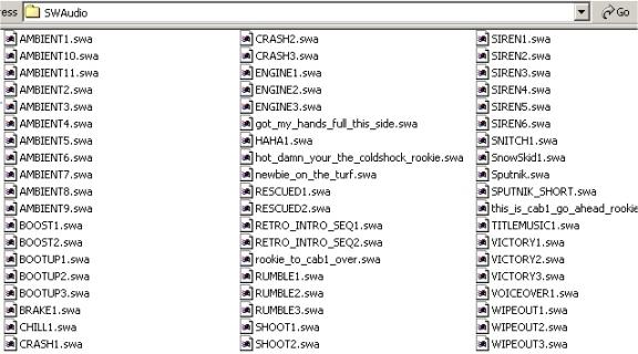
Figure 5.4.1 The final selection of sounds for the game
Sound foley by its very nature is
experimental. The only rule being that
there are no rules at all; the process is not all-important, the result
is. The majority of the sound effects
listed in Figure 5.4.1 were mouthed into a cheap microphone to begin with, or
in the case of the crashes were the result of banging various different metals
together. Once the original sounds have
been recorded, even if they only bear a passing resemblance to the sounds they
aspire to be, they can be pitch-bent, echoed, layered up, equalized and
convoluted until they reach the required sound. Sound Forge allows such a degree of control over the sound that
as often as not the processed sound bears no relation to the original.
The only draw-back to powerful sound
editors such as Sound Forge is that they do not work in real-time. Reasons’s NN19 sampler allows instant pitch
shifting and real time control over cutoff, resonance, modulation and the ADSR
envelope. When chained to a compressor,
two band equaliser and perhaps a delay and reverb unit, the sample can be
looped, while the various parameters are adjusted to bring the sound closer and
closer to its destination. By starting
with a different coloured noises (brown/pink noise etc.) the effects such as
the air-brakes were recorded with the nn19.
The engine noise too, is the result of dropping the pitch of a
Didjerido, time-stretching the result and adding a touch of distortion.
Not all the samples were created in
the above fashion, many are generated by the software synthesisors introduced
earlier, namely Stomper Ultra and Reaktor.
The victory samples were taken from the revolution folder in the Blue
Box sound effects collection. These
samples are segments extracted from a rally where an animated leader leads the
crowd to chant “El pueblo, unido, jamais será vencido”, or “The people, united,
never will be beaten”, a fitting war-cry for the team version of the game.
5.5 The soundengine
The soundengine written for the game is a wrapper to the sound API provided with Director. It provides a single point of entry into the sound system so that samples can be triggered from any script without worrying about the consequences. To play a sound in Director normally, a channel must also be selected. If every script that triggered a sound had to declare which channel that sound was to be played on, it would be very difficult to avoid conflicts between sounds. When the logic is distributed like this, the system becomes very difficult to expand. The soundengine centralises the logic, by exposing one single method that will play and manage a sound:
triggerSFX(me,effectType, intensity, num_loops)
The soundengine selects a sample and a channel based on the effect type. For example if the effect type is ‘crash’ it selects a sample at random from the bank of crash sounds and then attempts to play the sound in the first available sound channel.
Not all the sounds are handled in the same way. Internally there are four handlers, which provide for different situations. BreakPlay will wait until currently playing sample reaches its endpoint and then play. Queplay will wait until the currently playing sound has played its final loop. AmboPlay will queue a random ambient soundscape in channel seven.
on simplePlay(me,soundsamp,num_loops)
on breakPlay(me,channel,soundsamp,num_loops)
on quePlay(me,channel,soundsamp,num_loops)
on amboPlay(me,soundsamp,num_loops)
Figure 5.5.1 The four internal methods for playing sounds
Just like the game-engine then, the sound-engine is based on cause and effect. The scripts that trigger sounds during the course of the game are listed in figure 5.5.2.
|
Sound Effect: |
|
|
Raycast_jeep: keypress |
|
|
Raycast_jeep: keypress |
BOOST |
|
Raycast_jeep: accelerate |
ENGINE
1 OR 2 (revving or idle) |
|
Raycast_jeep: when upside for more than 2 seconds. |
RESCUED
(voice-over) |
|
Havok_catchers: when the disc comes within a threshold distance of the jeep |
SIREN1
or 2 depending on player |
|
Havok_catchers: when player pressed the shoot button |
SHOOT1 |
|
Havok_callback_handlers when the maxscore is reached by a player |
VICTORY1
OR 2 |
|
Havok_callback_handlers when a collision is detected between the two vehicles |
RUMBLE1 |
|
Hangback Camera when the angular velocity exceeds a certain threshold value |
WIPEOUT1 |
Figure 5.5.2 Cause and Effect from a sound point of view
5.6 The Beats System
As mentioned in the Design chapter, the initial plan with regard music was to design complimentary sets of beats that would layer up as the game progressed. In a sense it was hoped that the soundscape would contribute to the gameplay by giving a cue to the players as to how they are progressing. The beats system led to a number of technical avenues being pursued, including that of placing markers at the end of the loops that would trigger an event to check a stack to see if there were any additional loops to enter into the mix. When the latency beast reared its head, this approach had to be re-considered. In order to get a feel for what type of music would suit the game, it was played with various tracks composed in Reason running in the background, none of which seemed to gel with the gameplay. With the swing in the graphic tone brought about by the heightmap implementation, ambient sounds seemed to compliment these sparse levels well, providing an air of intrigue, and a sense of alternate reality.
5.7 The Ambient Path
Software synthesisers have recently achieved a level of realism that
renders them almost indistinguishable from their hardware counterparts. The Hammond B4 softsynth, apart from failing
to drift out of tune, provides a thoroughly convincing replication of the
original organ. Depending on the
quality of the soundcard however, there may be a noticeable interval between
depressing a note on the keyboard and the rendering of the actual sound. This can make melodic composition using
softsynths very tricky.
Composing ambient music however is different. Generally a root-note is held down for a length of time, while
the parameters are adjusted either using the mouse or a MIDI-controller. Other instruments such as the granular
instruments do not require MIDI input at all.
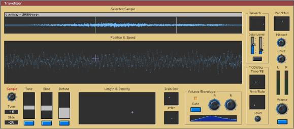
Figure 5.7.1 Snapshot of the travellizer granular synthesis instrument
The Travellizer shown in figure 5.7.1 is an implementation of a granular
synthesis instrument with a unique interface that comes with Reaktor. It takes advantage of the XY controller
boxes that allow two parameters to be mapped to the axes of a single
window. The larger “Position and Speed”
window for example controls where the instrument should start to extract
granules from the waveform and the speed at which this start position migrates
from it’s current position (sometimes called the glide). The green line in the waveform window shows
the start position for the granule selector and the white line represents the
end. The position of the white line,
along with the density of the granules is controlled by another XY-window. The interface is so well designed that it
feels ‘natural’. After a short time,
the user is well aware of the various effects achievable by moving the length
and density crosshair in a certain trajectory.
The instrument also comes with a simple attack-release volume envelope
for the granules, along with stereo coloured reverb, a triplet of tuner controls
and a simple delay.
If we consider each start position and length to be a window into the
waveform, then the grainstate instrument shown in figure 5.7.2 allows us to
play a series of these windows in sequence.
In the top-righthand section of the instrument up to 8 scenes can be
placed in a timeline. Each scene’s
length and position in the waveform is then set in the 8 scene memories. The synthesiser cycles through these scene
positions at a certain rate, bringing out different textures from the chosen
sample to create entirely new sounds.
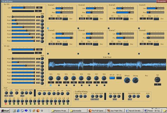
Figure 5.7.2 Snapshot of the grainstate instrument – a sequenced granular synth
5.8 The title music
The title music is important in setting the mood and the scene for the
game. It gives a subconscious
indication of the type of game, and even helps us to fill in the blanks in the
game world that has been created. The
title track was composed in Reason, and features many of the beats that were to
make it into the game proper. Some of
the more musical sound effects were actually extracted from the title
track. The track itself uses techniques
such as the slow-pitch bend to drop instruments slightly out of tune
momentarily, and incorporates a tranquil mid-section to contrast with the beats
that dominate the rest of the piece.
5.9 Summary
This chapter opened with a general note on the importance of sound in video games, and then addressed the specific implementation issues regarding sound in Director. This was concluded with a description of some of the sound-foley techniques used and the reasoning behind abandoning Reason.
Chapter 6
Conclusion
6.1 Introduction
The final chapter in the report focuses on the results of the project with respect to the initial aims.
6.2 The evolution of the game design
The making of the game was a journey involving a great many turnarounds, revelations, successes and frustrations. When one is not an expert in an area to begin with, it is impossible to guard against the unknown. Who would have known about the internal conversion to inches applied by 3D Studio Max, or the limited number of sound channels, or the inefficiencies of the raycast command? In fact, the only way to become an expert is to make all these mistakes in the first place. An absolute plan from the beginning would have required that the author was already an expert in the areas of 3D modelling, in-game physics, and sound design, whereas the purpose of the project was to learn about these processes. This chapter discusses the ideas that got left behind, and then looks forward at the next steps to be taken.
6.3 The ones that got left behind
Possibly the biggest exclusion from the current version of the game is that of the networking component. A network drive model was written in conjunction with a game server, so that a player would be in control of a vehicle on the local machine and on another machine on the network. A network is unlikely to be fast enough to be able to transmit the player’s entire status during every frame, as this would congest the line. Instead only the keystrokes are sent, as these change at a much slower rate than the player’s position and rotation. To make it even more efficient only two messages are sent per keystroke - keyDown and keyUp, in the same fashion that midi notes are transmitted. In terms of throughput on the network the data-size is miniscule, the problem is that the two physical simulations running on the two machines begin to ‘drift’. Even on the fastest of networks, this occurs. The reason being that the Xtra version of the physics engine is not entirely deterministic – it is chaotic. As such, the players end up playing two separate games. To combat this, one version of the game needs to be established as the ‘correct’ version, to which the other versions periodically syncronise. If the re-syncing frequency is too high, the network will congest, and if it is too low, the games will drift apart. In addition, if the system is constantly setting the position of a physical entity instead of applying impulses or forces to it, it nullifies the work of the physics engine, so care must be taken when setting the re-sync frequency.
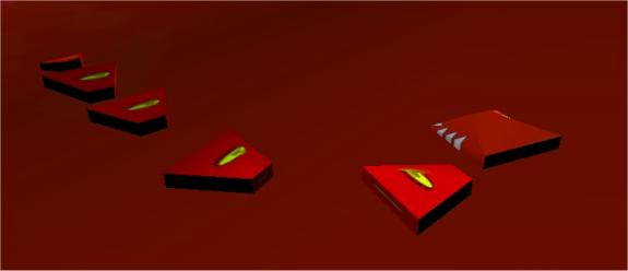
Figure 6.3.1 The psuedo-simulated snake character
Another one that got away was the snake character, an unyielding baddy character that followed a path specified in an animation, but still continued to interact with the physics engine by knocking anything it encountered out of its way. The snake was a six segment character which consisted of a head, four body segments and a tail, with each part being connected to the next using a linear dashpot. Only the head was animated, which allowed the motion of the rest of the body to emerge from the physics engine to produce extremely lifelike movement. The development of this character raised the issue of blending animation and physics together. The same blending techniques were then used to allow the augmentations (which were animated models) to interact with the physics, which can be seen in figure 6.3.2. The blending of animation and physics has become a large area in the animation and game industries as both a time-saver and creator of natural looking secondary motions.
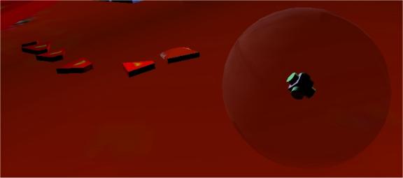
Figure 6.3.2 An animated augmentation spinning around inside its physical proxy.
6.4 Known Issues & Future Work
There are a few known issues regarding the game at the current moment, the main concern being that the aspired to frame-rate of 45 is rarely reached, as the game tends to average a rate of 30 frames per second. The car at times seems unstable which is perhaps to be expected when a jeep with a high centre of gravity is driven at 180 kilometres an hour over unnaturally severe terrain. To combat these problems, perhaps it would be better to revert to a sliding block drive model and the original characters, thus removing the raycast from the equation entirely. It would then be possible to realise the game as a network based four-player team game. The levels could still be generated using heightmaps, and in terms of design the game would have come full circle.
The only other alternative is to lower the center of gravity of the vehicle to the wheelbase, or to introduce an invisible pendulum connected to the chassis to stabilise it on extreme turns. With the release of Director 9, the raycast command may indeed be fast enough to execute 18 times a frame, without posing a significant performance hit.
With regard to sound, it may be possible to directly access the parameters of the DirectX versions of the Reactor instruments, using DirectAudio8. If this were the case, it would be possible to use data from the physics engine such as positions and velocities to feed directly into the parameters of the granular synthesiser and other instruments. Thus, the soundscape would be synthesised in real-time, which while this would mean incurring a performance hit, would allow for a relationship between the sounds being played and the relative positions of the game characters to emerge. This interaction of sound and gameplay aids the players in their awareness of the other players’ positions.
The 3D positional audio component is also an attractive route to follow as in this way, associating a distinctive vehicle sound with each player could further enhance each character’s unique identity. As mentioned earlier, effects such as Doppler-shift etc. then fall out of the system, allowing the game to take place in a more convincing world.
In order to aid others that wish to make a game in Director or to improve on this game, the source is to be made available on the web (www.maths.tcd.ie/~bricklem). As it stands at the moment, many files such as the heightmaps, sound effects and backdrops are left as external files so that those interested can replace the levels with their own creations.
6.7 Conclusion
The
aim of the project was to create a prototype 3D computer game where the physics
and soundscape were paramount.
Initially, the characters were designed so that all their components
were physically active, and later it was realized that this is not always
necessary. The potential for added
value in gameplay however, is only limited by the game designer’s sense of
experimentation. Once the game proper
is in place we can allow characters to attach themselves to other characters by
springs, apply a perfect co-efficient of restitution to a sphere to enable it
to bounce forever (a quick obstacle course perhaps) and much more. A suitable sound for the game emerged over
the course of the project, when the hard hitting beats of Reason were forsaken
for the rich ambient textures of Reaktor.
Although the project itself was broad in its nature,
I hope that this document has helped to highlight the key elements, and convey
the lifecycle of the game making process.
The project itself was certainly a journey of discovery. If I had known at the offset what I know
now, perhaps different decisions would have been made. This document told the story of the journey,
from the ambitious beginnings, through the shifts in design to the in-depth
implementation of the realized game.
This chapter dealt with the parts that almost made it as the game, the
game as it stands, and its future.
Glossary of terms:
Lingo:
The native programming language of Macromedia’s Director product.
Sprite:
An instance of a cast member on the stage is called a sprite. You can have many different versions (sprites) of a cast member on stage at any one time. This might be useful if you want to have multiple versions of a picture in an animation, all of different sizes, moving in different directions.
Handler:
A piece of code that performs a single logical function e.g. a mouseDown handler will do something when the user clicks the button on the mouse.
Bibliography:
David M. Bourg, Physics for Game Developers, O’Reilly. (2002)
Tim Kientzle, A Programmer’s Guide To Sound, Addison Wesley. (1998)
Alan Douglas, The Electronic Musical Instrument Manual – a guide to theory and design.(1990)
Eduardo R.
Miranda, Computer Sound Synthesis for the
electronic musician, Oxford. (1998)